How Do You Get Such Good Audio?
Larry Higgins, W5EX
Intertie, Inc., San Antonio, Texas
How does Intertie achieve such good audio with 22 linked repeaters? This question, asked some time ago, by one of our most experienced Members, is worthy of a clear answer. I’m going to share what I have learned over the last 35 years or so.
Background
First, our system is analog frequency modulation. FM has always been known as a high-fidelity mode. Indeed, years ago, land mobile services audio with wide-band modulation, was of nearly broadcast quality. At that time, our link radios were capable of 15 Khz deviation. When the FCC demanded a narrower channel width, in order to accommodate more licensees, the manufacturer obeyed: first 5 Khz, and now, down to 2.5 Khz ! Voice transmissions showed immediate degradation with the narrower bandwidth. More careful management to avoid speech clipping was helpful in preserving intelligibility, but the full-throated bass and treble response we previously enjoyed were gone forever.
Because the FCC does not dictate FM bandwidth to Amateurs, we could still use the wide-band radios, but their numbers have shrunk to minuscule with age and availability. Right now, 5 Khz is still available in some current radios, via software selection. We select this option, always.
Linked System Requirements
FM depends on a fully quieted signal path for best sound. So in linking radios we must first assess the path loss , then provide antennas and feedlines of high enough quality to achieve a 20 dB fade margin. This is tested by inserting a step attenuator into the receiver transmission line and clicking in calibrated resistors until the link becomes unintelligible, then more attenuation until the link extinguishes. In actual practice, we obtain an incoming signal bet calling for dial tone from the next site in the chain, [or key-up provided by another operator from a site upstream] then crank in attenuation until the COS indicator goes out. The decibels displayed in the attenuator at that point we label as our fade margin. Realistically, 20 dB is not always achieved, but that is our goal. A weak RF link will provoke varying degrees of audio distortion. We don’t want that!
Once we are receiving a fully quieted signal, we want the received audio to sound like a local repeater user. How do we do that?
Our Secret of 35+ Years
Here is the secret: re-transmit flat audio. Our mentors in this concept are members of the California-based Cactus Intertie, of which we are an affiliate. Here are the steps: You as a user transmit audio that has been pre-emphasized, a process wherein circuitry is inserted in the audio path from microphone to transmitter that intentionally favors higher audio pitch. This is a necessary artifact of the frequency [phase] modulation scheme that we use. Consult a radio text for further explanation.
At the link site, we receive your pre-emphasized audio and then undo the processing with a de-emphasis circuit. This audio can be amplified and sent to a local speaker. After de-emphasis, the audio sounds natural: without de-emphasis, it would sound tinny in the local speaker.
In properly linked systems, we snatch the audio before it is de-emphasized, amplify it, and send it [still pre-emphasized] along to another FM transmitter, directly to the modulator, without further pre-emphasis. This means that the pre-emphasis inserted in your personal radio containers to affect the transmitted audio.
After being received at the distant link, the audio modulates the distant attached repeater. This repeater re-transmits the pre-emphasized audio to my personal radio, wherein (at last) the audio en route to my radio’s speaker is de-emphasized.
There it is - our simple system works extraordinarily well!
So what Else Do we Do to the Radios?
Now, you ask, do you ever tweak the audio just a little? Yes, of course, for 2 reasons:
For linearity within a given receiver or transmitter
To cure distortion
Transmitters available to us to date varied greatly in modulation quality. That available in the extinct Motorola Motrans was true FM and was a joy to work with. The equally extinct GE EXEC-II exciters featured phase modulation and have a notoriously poor low frequency response. The later MASTR II and its contemporary Motorola Micor produced much cleaner audio. We are currently looking into more recent radios.
We found there was little we could do to improve frequency response on the transmitter side, except to keep the modulation in the 4-5 Khz range, avoiding > 5 KHz spikes.
In the case of receivers, we have found failed capacitors to be a potent cause for distortion and non-linearity. Rarely, inductors fail. In the case of the Motorola Motrac/Motrans the IF (intermediate frequency) filter may fail. (so-called “Permakay” filter).We always disable to AFC (automatic frequency control) in all receivers. We make certain that all transmitters and receivers are on frequency. This requires taking account of ambient temperature in warping crystals. Manufacturers provide charts for this purpose. In recent years we have spent additional money to have the crystal channel elements factory-tweaked - an expensive addendum.
The radios cited are all obsolete, but still comprise the majority of our stations. The far newer frequency synthesized radios will be taking their place. They are computer-programmable, thus no more crystals to order. But they cannot be duplexed in the case. Their predecessors were easily converted to full duplex. The end result is that we must purchase 2 radios per link channel pair, as opposed to only 1 in the past. We are currently evaluating their audio frequency response as they come from the factory. We are finding that it is not perfect and that, as a result, shaping networks will be required.
What Else Do We Need to Link Up?
: Generating Squelch Signal
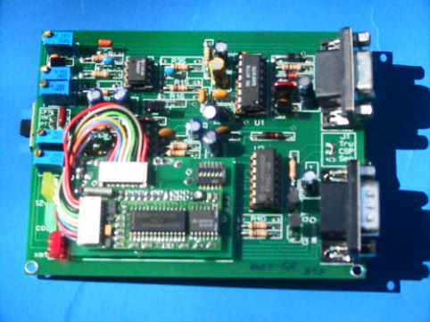
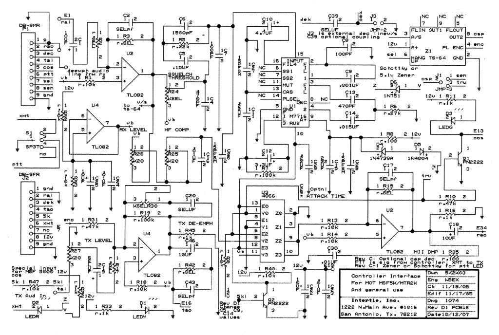
There are 2 more necessary elements in a linked system: the controller and the audio processor/switcher. With the exception of the now extinct Palomar Telecom controllers, all available, linked duplex radio compatible controllers require that we supply COS (carrier operated squelch) and clean, switched audio from receiver to transmitter (s). We accomplish these tasks with an external accessory interface. In its original incarnation, designed by Armadillo Intertie member, Jim, WD5IYT (SK), the design was centered on the Motorola M7716 Micor squelch chip. Incoming discriminator audio keys the Micor chip logic to provide clean switching of received audio. The Micor chip keys a 4066 CMOS switch. This was an excellent choice, because there is essentially no cross-talk with its 80 dB isolation.
Management of Received and Transmitted Audio
The real genius in the board design is in the audio passband adjustment afforded by and op-amp coupled to RC networks. The potentiometers allow us to adjust for a linear audio response at 2 test points - 1000 Hz and 3000 Hz. Levels are set to a system-wide standard of 40% usable modulation, viz.:
Receiver: On-frequency 50 µV signal, 1000 Hz and 3000 Hz modulation at 2 KHz deviation; Set to -10 dBM at 600 ohms at each modulating frequency.
Transmitter: Modulate to -10 dBM at 1000 Hz and 3000 Hz; Adjust deviation to 2 Khz at each modulating frequency.
Although this seems like a very sketchy, even primitive system approach, it is surprisingly good. It is possible to maintain flat audio from most receivers between 300 Hz and 3000 Hz ± 0.5 dB, which meets the audio standards of the Cactus Intertie Radio system. Most importantly, the board allows us to interchange radios on the fly, without regard to radio manufacturer -and - if the audio is set up correctly - to do so without instruments carried to the site. The illustrations show schematics and illustrations of our current [“5K2K03”] audio/squelch/CTCSS boards.
.
We Still Need to Distribute Audio and PTT signals: Controllers
The associated controller must maintain this audio pass-through quality. All currently available duplex multi-link controllers achieve or exceed the standard. Once again, this required careful management of op-amp circuitry and clean audio and transmitter switching.
The illustrations show some work we did a number of years ago to reassure ourselves that our own designs were up to specification. In doing these tests, we found that additional tweaking of come components in our own I-Square controller was quite helpful. Upgrades to similar circuitry found in the Palomar controllers were published buy the Cactus Intertie several years ago. With more modern op-amps and 3 decades of designer experience, the new Sierra Radio Systems controllers exceed specifications,
Conclusion
With the support of colleagues in the Cactus Intertie and Armadillo Intertie, our group has successfully built and installed a system of 22 linked FM repeaters. We now share the secret of our successful transport of clean audio from end to end - distance of over 600 miles.
All text, illustrations, graaphs, drawings are copyright October, 2016, Intertie, Inc.